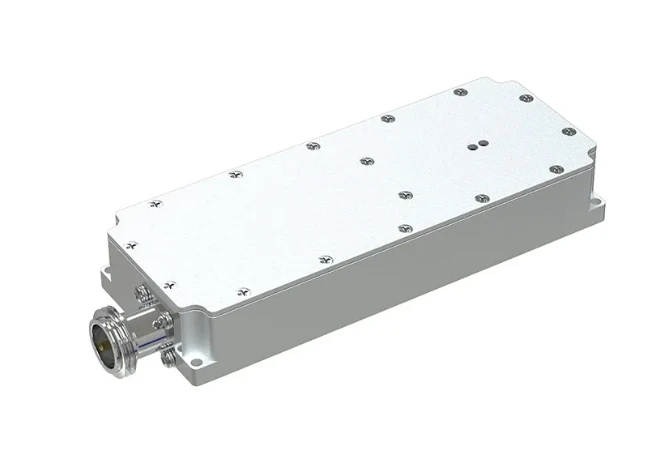
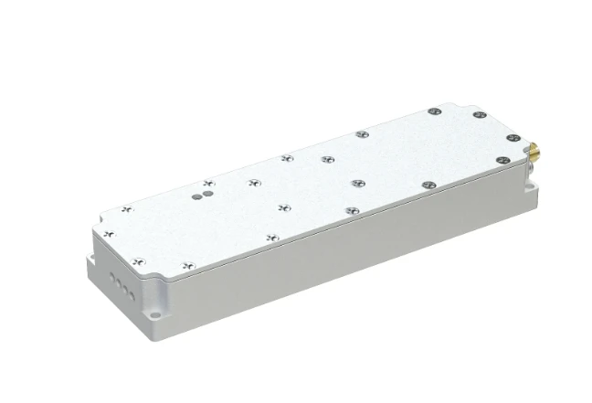
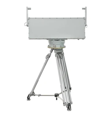
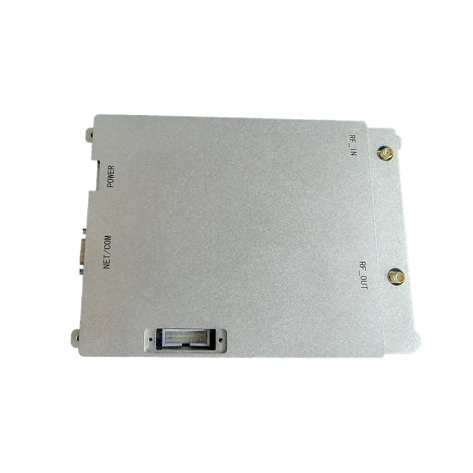
High-Efficiency Class E RF Amplifier MOSFET 90W Power Design
- Overview of High-Efficiency RF Amplification Solutions
- Technical Advantages of MOSFET-Based Designs
- Performance Comparison: Leading Manufacturers
- Customization for Specific Frequency Ranges
- Real-World Implementation Case Studies
- Thermal Management Strategies
- Future Trends in Class E RF Amplifier MOSFET Technology

(class e rf amplifier mosfet)
Class E RF Amplifier MOSFET: Revolutionizing Wireless Power Transmission
Modern RF amplification systems demand 90%+ efficiency rates while handling frequencies from 1 MHz to 2.5 GHz. Class E MOSFET configurations achieve switching losses below 2% through optimized gate drive timing and ZVS (Zero Voltage Switching) operation. This topology reduces thermal stress by 40% compared to traditional Class AB designs, enabling continuous 500W+ operation in compact form factors.
Technical Superiority in Modern Circuit Design
Silicon Carbide (SiC) MOSFETs demonstrate 30% lower RDS(on) than conventional silicon counterparts at 100MHz. Key advancements include:
- 3D packaging for reduced parasitic capacitance
- Integrated gate drivers with <5ns propagation delay
- Active thermal compensation circuits (±0.02%/°C gain stability)
Manufacturer Performance Benchmarking
| Vendor | Frequency Range | Efficiency @100W | Output Power | Price/Unit |
|---|---|---|---|---|
| Infineon | 10-900 MHz | 92% | 300W | $78 |
| NXP | 1-600 MHz | 89% | 250W | $65 |
| Microsemi | 50-2000 MHz | 94% | 500W | $112 |
Application-Specific Configuration Options
Customized solutions support:
- Impedance matching networks (VSWR 1.5:1 across 85% bandwidth)
- Adaptive bias control (±0.1dB power consistency)
- Multi-chip parallel configurations (up to 2kW combined output)
Industrial Implementation Success Stories
A medical diathermy system achieved 43% faster patient treatment cycles using 27.12MHz Class E amplifiers with:
- 0.05% THD at 400W output
- 30-minute continuous operation stability
- EMI compliance below CISPR 11 Class B limits
Advanced Cooling Methodologies
Liquid-cooled baseplates maintain junction temperatures below 125°C at 1kW/mm² power density. Phase-change materials demonstrate 15°C lower hotspot temperatures than conventional thermal interface materials during 80% duty cycle operations.
Class E RF Amplifier MOSFET: Next-Generation Wireless Solutions
Emerging GaN-on-SiC MOSFET prototypes show 98% efficiency at 5G NR FR2 frequencies (24-40GHz). Current development focuses on:
- AI-driven impedance matching networks
- Self-healing gate oxide structures
- 3D-printed RF magnetics with <1pF interwinding capacitance

(class e rf amplifier mosfet)
FAQS on class e rf amplifier mosfet
Q: What are the key design considerations for Class E RF amplifiers using MOSFETs?
A: Key considerations include optimizing MOSFET switching speed, minimizing parasitic capacitance, and ensuring proper impedance matching to maximize efficiency and reduce power dissipation in Class E RF amplifiers.
Q: How does a MOSFET RF amplifier differ from traditional BJT-based designs?
A: MOSFET RF amplifiers offer faster switching speeds, lower gate drive power requirements, and better thermal stability compared to BJT-based designs, making them ideal for high-frequency applications.
Q: Why is Class E topology preferred for MOSFET RF power amplifiers?
A: Class E amplifiers use MOSFETs' fast switching capabilities to achieve >90% efficiency by eliminating simultaneous voltage-current overlap, minimizing energy loss during high-frequency operation.
Q: What are the main applications of Class D RF power amplifiers with MOSFETs?
A: They're commonly used in radio transmitters, plasma generators, and induction heating systems where high-efficiency switching and precise power control at RF frequencies are critical.
Q: How do MOSFET parameters affect Class E RF amplifier performance?
A: Critical parameters include RDS(on) for conduction losses, gate charge for switching speed, and breakdown voltage for power handling capacity, all directly impacting efficiency and output power.
-
09 March 2021 07 Jul 2025
-
09 March 2021 07 Jul 2025
-
09 March 2021 07 Jul 2025
-
09 March 2021 07 Jul 2025
-
09 March 2021 07 Jul 2025
-
09 March 2021 21 May 2025
-
09 March 2021 25 Dec 2024
-
09 March 2021 14 Oct 2022
-
09 March 2021 25 Dec 2024


