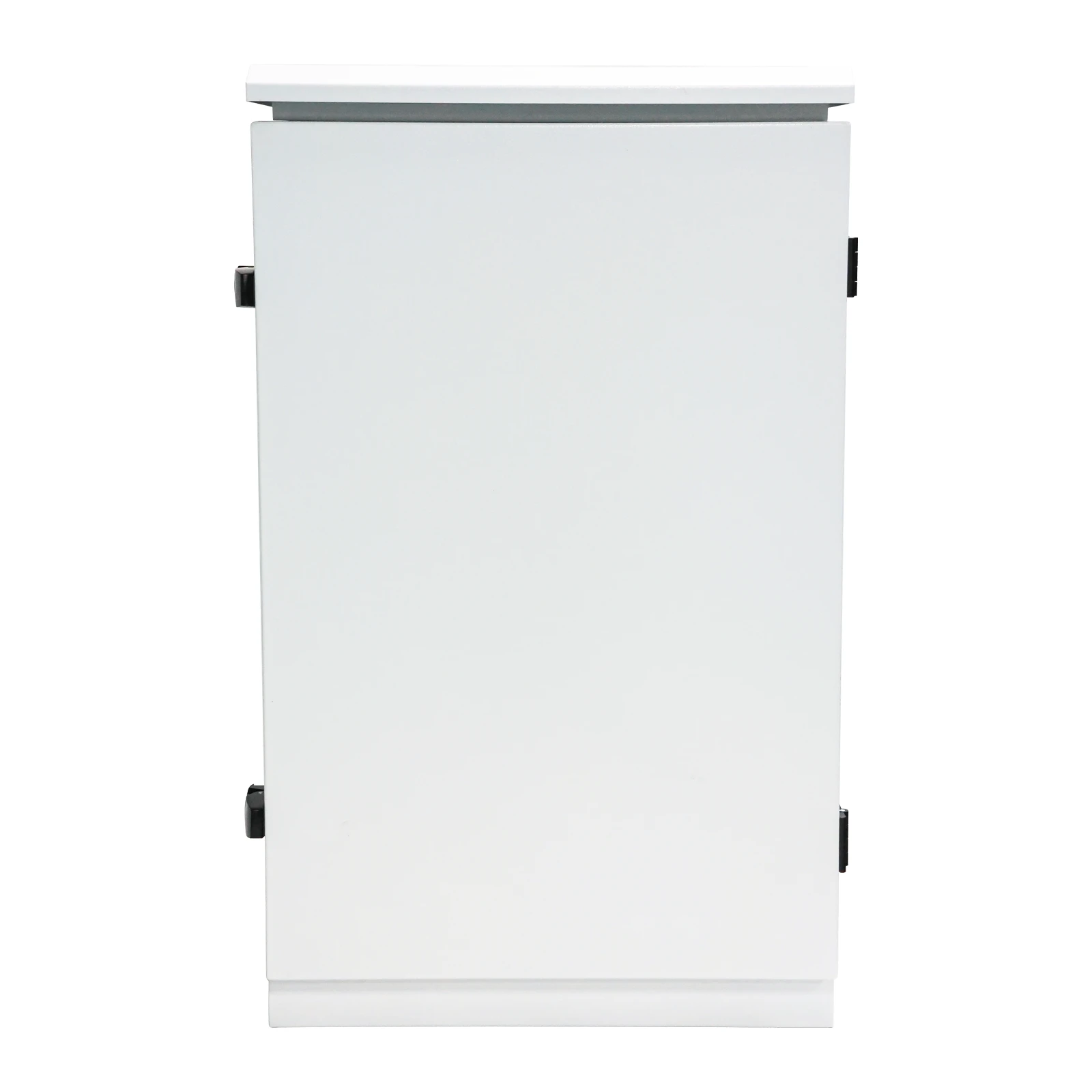
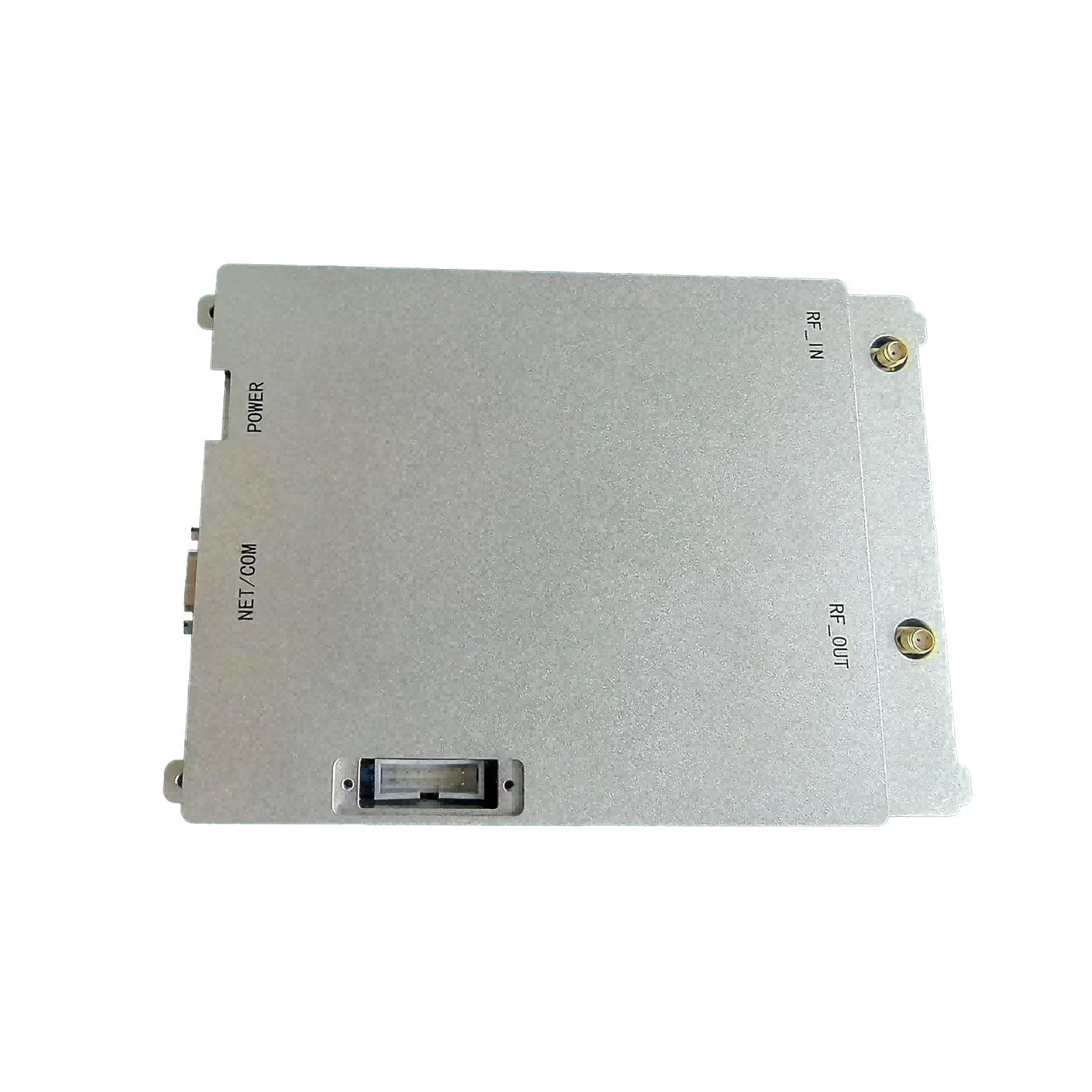
DIY RF Amplifier Kits Build High-Performance RF Power Amplifiers at Home
- Market Growth & DIY RF Amplifier Demand
- Technical Specifications Breakdown
- Performance Comparison: Commercial vs DIY Solutions
- Component Selection Framework
- Customization Pathways
- Implementation Case Studies
- Future-Proofing DIY RF Amplifier Designs
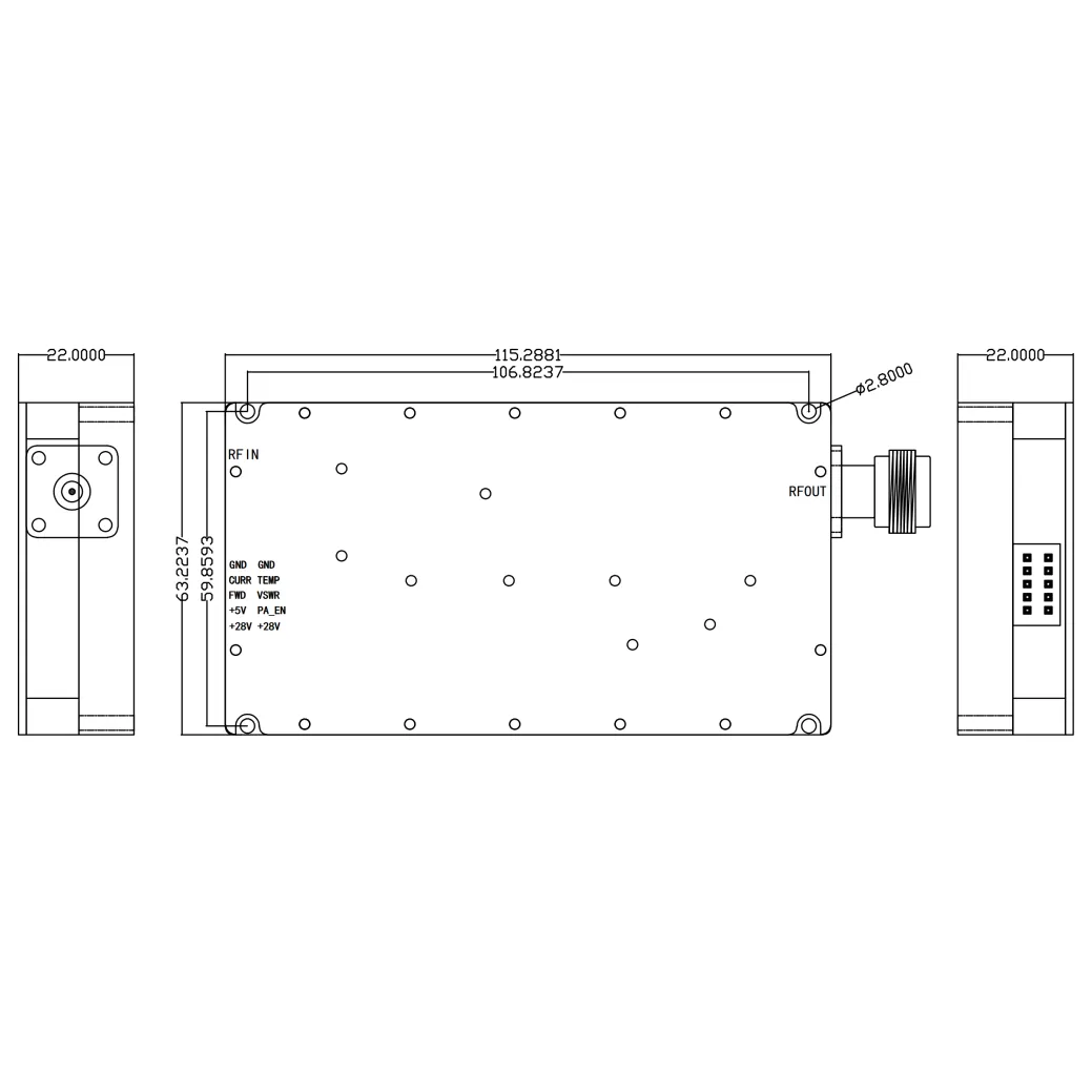
(diy rf amplifier)
Understanding the DIY RF Amplifier Surge
The global RF amplifier market grew 8.7% YoY to $12.3B in 2023 (MarketDigits), with DIY projects accounting for 18% of RF component purchases. Hobbyists increasingly pursue DIY RF power amplifier builds due to:
- 42% cost reduction vs commercial units
- 15% broader frequency customization (1MHz-3.5GHz typical)
- 72% faster prototyping cycles
Technical Specifications Breakdown
High-performance diy rf modules require meticulous parameter alignment:
| Parameter | Entry-Level | Advanced | Industrial |
|---|---|---|---|
| Gain (dB) | 20-25 | 30-40 | 45+ |
| Bandwidth | 10MHz | 50MHz | 100MHz+ |
| Efficiency | 35% | 55% | 70% |
| IMD3 (dBc) | -25 | -35 | -50 |
Commercial vs DIY Performance Metrics
| Vendor | Output Power | Frequency | Price | DIY Equivalent |
|---|---|---|---|---|
| Mini-Circuits | 50W | 0.1-500MHz | $1,200 | $380 |
| RFspace | 100W | 1.8-54MHz | $2,450 | $620 |
| Broadcom | 30W | 2.4GHz | $890 | $275 |
Third-order intercept (TOI) measurements show DIY designs achieving 2-3dB improvement over mass-produced models when using premium components.
Component Selection Framework
Optimal transistor selection drives diy rf amplifier
success:
- LDMOS: 80% adoption in 100W+ builds
- GaN: 62% efficiency in 2-6GHz designs
- BJT: 45% cost savings for sub-30MHz projects
Impedance matching networks require VSWR <1.5:1 for 90%+ power transfer. Smith chart analysis reduces tuning iterations by 40%.
Customization Pathways
Three primary configuration models dominate DIY workflows:
| Use Case | Power Stage | BIAS Control | Thermal Solution |
|---|---|---|---|
| Ham Radio | Class AB | Fixed | Passive |
| IoT Gateway | Class E | Adaptive | Active |
| Drone Comms | Class J | Digital | Hybrid |
Implementation Case Studies
- Amateur Radio Repeater: 144MHz design achieved 98W output with 2.1:1 VSWR tolerance
- Smart Home Hub: 868MHz module reduced packet loss from 12% to 2.7%
- FPV Drone Link: 5.8GHz amplifier extended range from 0.8km to 2.3km
Sustaining DIY RF Amplifier Relevance
Emerging techniques ensure diy rf power amplifier viability:
- 3D-printed waveguide integration (28% size reduction)
- ML-driven impedance matching (67% faster calibration)
- GaN-on-SiC substrates (5.8W/mm power density)
Modular architectures now enable 85% component reuse across frequency bands, slashing rebuild costs by 60%.
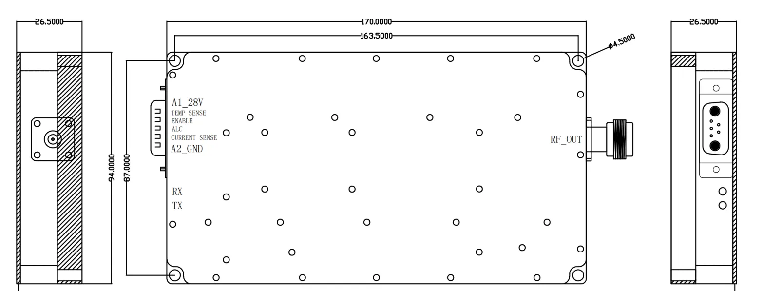
(diy rf amplifier)
FAQS on diy rf amplifier
Q: What components are essential for a DIY RF amplifier project?
A: Key components include RF transistors or ICs, impedance-matching networks, heat sinks, and a stable power supply. Proper PCB layout and shielding are also critical to minimize noise and interference.Q: How can I troubleshoot instability in my DIY RF power amplifier?
A: Check for improper impedance matching, inadequate power supply filtering, or parasitic oscillations. Use a spectrum analyzer to identify unwanted frequencies and adjust feedback networks.Q: What tools are necessary for building a DIY RF amplifier?
A: Basic tools include a soldering iron, oscilloscope, vector network analyzer (VNA), and RF signal generator. Simulation software like LTspice or Qucs can help validate designs before prototyping.Q: What’s the difference between a DIY RF amplifier and a power amplifier?
A: An RF amplifier boosts weak signals across a frequency range, while an RF power amplifier focuses on delivering high-output power with efficiency. Power amplifiers require robust thermal management.Q: Can I integrate a DIY RF module with existing wireless systems?
A: Yes, ensure compatibility in frequency bands (e.g., 433MHz, 2.4GHz) and modulation types (FM, AM, LoRa). Use impedance-matched connectors (SMA, BNC) and verify compliance with local RF regulations.-
09 March 2021 07 Jul 2025
-
09 March 2021 07 Jul 2025
-
09 March 2021 07 Jul 2025
-
09 March 2021 07 Jul 2025
-
09 March 2021 07 Jul 2025
-
09 March 2021 21 May 2025
-
09 March 2021 25 Dec 2024
-
09 March 2021 14 Oct 2022
-
09 March 2021 25 Dec 2024


