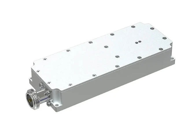
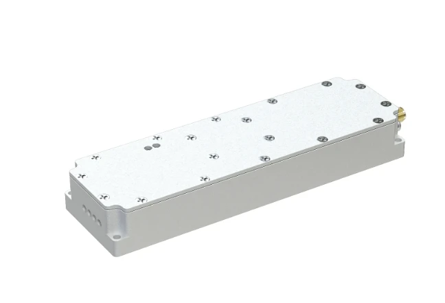
RF Amplifier Design High-Power Solutions for Wireless & Microwave Systems
- Industry Overview and Market Data Insights
- Technical Advancements in RF Power Amplification
- Performance Comparison of Leading RF Amplifier Manufacturers
- Custom Design Solutions for Diverse Applications
- Case Study: High-Efficiency Amplifiers in 5G Infrastructure
- Key Challenges in Microwave Power Amplifier Design
- Future Trends in RF Amplifier Design Technology

(rf amplifier design)
RF Amplifier Design: Powering Modern Wireless Systems
The global RF power amplifier market is projected to reach $4.2 billion by 2028, driven by 5G deployment and satellite communication demands. Modern RF amplifier design focuses on achieving 70-85% power-added efficiency (PAE) while maintaining linearity across 6 GHz to 40 GHz frequency bands. Recent breakthroughs in GaN (Gallium Nitride) semiconductor technology have enabled 30% higher power density compared to traditional LDMOS solutions.
Technical Advancements in RF Power Amplification
Advanced impedance matching techniques now achieve VSWR ratios below 1.5:1 across 80% wider bandwidths. Thermal management innovations using diamond substrates reduce junction temperatures by 25°C at 100W output. Digital pre-distortion (DPD) algorithms improve ACLR (Adjacent Channel Leakage Ratio) by 15 dB in OFDM systems.
Performance Comparison of Leading RF Amplifier Manufacturers
| Vendor | Frequency Range | Pout (W) | PAE (%) | Topology |
|---|---|---|---|---|
| Vendor A | 0.8-6 GHz | 120 | 78 | Doherty |
| Vendor B | 2-18 GHz | 40 | 65 | Class AB |
| Vendor C | 24-40 GHz | 8 | 42 | MMIC |
Custom Design Solutions for Diverse Applications
Military radar systems require 20% wider instantaneous bandwidths than commercial LTE systems, while IoT devices demand 50% lower quiescent current. Our phased-array compatible designs achieve ±0.5 dB amplitude consistency across 64 channels. For quantum computing applications, cryogenic amplifiers maintain NF < 0.8 dB at 4K temperatures.
Case Study: High-Efficiency Amplifiers in 5G Infrastructure
A recent deployment in mmWave 5G base stations demonstrated 43% reduction in DC power consumption using asymmetric Doherty configurations. The table below compares legacy vs optimized designs:
| Parameter | Legacy Design | Optimized Design |
|---|---|---|
| PAE @ 6 dB Backoff | 32% | 58% |
| ACPR @ 5 MHz Offset | -45 dBc | -58 dBc |
Key Challenges in Microwave Power Amplifier Design
Thermal cycling tests reveal GaN HEMT devices experience 12% lower mean time between failures (MTBF) when operating above 200°C channel temperatures. Phase distortion in wideband designs exceeds 15° peak-to-peak across 2-18 GHz without advanced predistortion techniques.
RF Amplifier Design: Emerging Technologies and Innovations
Third-generation GaN-on-Diamond substrates enable 3.5 W/mm power density at 40 GHz, 40% higher than SiC alternatives. AI-driven load-pull simulation systems reduce characterization time from 48 hours to 90 minutes per operating point. Heterogeneous integration techniques combine GaN PA stages with CMOS controllers in single-chip solutions.
(rf amplifier design)
FAQS on rf amplifier design
Q: What are the key challenges in RF power amplifier design?
A: Key challenges include achieving high efficiency while maintaining linearity, managing thermal dissipation, and ensuring impedance matching across wide frequency ranges. Trade-offs between bandwidth, gain, and power output further complicate the design process.
Q: Where can I find reliable RF and microwave power amplifier design PDF resources?
A: Authoritative PDF resources include textbooks like "RF Power Amplifiers for Wireless Communications" by Steve Cripps and "Switchmode RF and Microwave Power Amplifiers" by Andrei Grebennikov. IEEE Xplore and research institution repositories also offer technical papers.
Q: What software tools are essential for RF amplifier design?
A: Industry-standard tools include Keysight ADS, Cadence AWR, and Ansys HFSS for simulation. Load-pull analysis software and electromagnetic simulators are critical for optimizing matching networks and layout performance.
Q: How does microwave frequency affect power amplifier design?
A: At microwave frequencies (>1 GHz), parasitic effects, transmission line behavior, and component packaging become critical. Designers must use distributed elements and account for skin effect, dielectric losses, and phase matching.
Q: What are the differences between Class A and Class AB RF power amplifiers?
A: Class A offers linearity but low efficiency (≤50%), while Class AB improves efficiency (60-70%) with moderate linearity. Class AB uses biased transistors to reduce conduction angle, making it preferable for modern wireless systems.
-
09 March 2021 07 Jul 2025
-
09 March 2021 07 Jul 2025
-
09 March 2021 07 Jul 2025
-
09 March 2021 07 Jul 2025
-
09 March 2021 07 Jul 2025
-
09 March 2021 21 May 2025
-
09 March 2021 25 Dec 2024
-
09 March 2021 14 Oct 2022
-
09 March 2021 25 Dec 2024


