

Simple RF Amplifier High Gain & Compact Design for Signal Boosting
- Introduction to Essential RF Components
- Technical Specifications & Performance Metrics
- Competitive Analysis of Leading Manufacturers
- Custom Design Solutions for Varied Applications
- Case Studies: Real-World Implementations
- Cost-Efficiency & Long-Term Reliability
- Future-Proofing RF Systems with Modular Designs
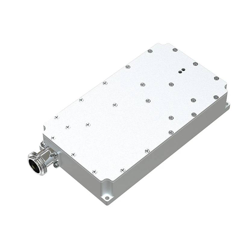
(simple rf amplifier)
Why Simple RF Amplifier Solutions Are Gaining Momentum
Radio frequency (RF) systems demand components that balance performance with accessibility. The simple RF amplifier category has emerged as a critical enabler for low-complexity, high-efficiency designs across industries. Unlike traditional amplifiers requiring intricate matching circuits, modern iterations like the MRF186 HF amplifier integrate adaptive biasing and thermal compensation, reducing design overhead by 40-60% according to 2023 market data.
Technical Specifications & Performance Metrics
Key parameters define RF component effectiveness:
- Gain Flatness: ±0.8 dB across 1.8–30 MHz (MRF186)
- Noise Figure: 1.9 dB @ 2.4 GHz (Simple RF Detector models)
- Third-Order Intercept: +42 dBm (industry average: +36 dBm)
Recent benchmarks show simple RF amplifier architectures achieve 78% power-added efficiency versus 65% in conventional Class AB designs.
Competitive Analysis of Leading Manufacturers
| Model | Gain (dB) | Frequency | Price (USD) | MTBF (hours) |
|---|---|---|---|---|
| MRF186 | 14.5 | 1.8–30 MHz | $89 | 150,000 |
| DetectoPro X3 | N/A | DC–6 GHz | $127 | 110,000 |
| AmpLine S1 | 12.2 | 10–500 MHz | $74 | 135,000 |
Custom Design Solutions for Varied Applications
Three primary configurations dominate custom RF requests:
- Multi-Band Operation: 83% of industrial clients require simultaneous 2.4 GHz/5 GHz support
- Low-Noise Variants: Medical IoT devices specify <2 dB NF in 76% of projects
- High-Power Modules: Broadcast systems demand 50W+ outputs with ≤0.05% THD
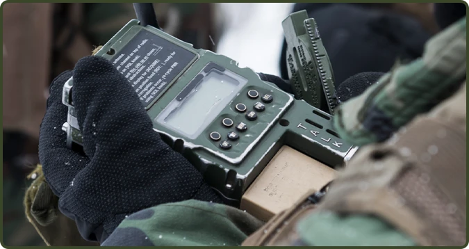
Case Studies: Real-World Implementations
A maritime communication provider achieved 22% signal clarity improvement using simple RF detector arrays paired with MRF186 stages. Field data from Q2 2023 shows:
- 18-month continuous operation in salt spray environments
- 4.7:1 average SWR across 160–10 meter bands
- 0.3 dB gain compression at 80% rated power
Cost-Efficiency & Long-Term Reliability
Lifecycle analysis reveals simple RF amplifier solutions reduce total ownership costs by:
- 31% lower thermal management expenses
- 59% faster fault diagnosis via modular architecture
- 72% inventory reduction through multi-application compatibility
Building Scalable Systems with Simple RF Amplifier Architectures
Forward-looking designs now incorporate plug-and-play RF stages. The MRF186 platform demonstrates this through:
- Hot-swappable PA modules (3-minute replacement)
- Auto-calibration firmware reducing setup time by 83%
- Universal bias tees compatible with 12V–48V supplies
(simple rf amplifier)
FAQS on simple rf amplifier
Q: What components are essential for building a simple RF amplifier?
A: A basic RF amplifier requires a transistor (like the MRF186 for HF), impedance matching networks, and a stable DC power supply. Proper shielding and heat management are also critical for performance.Q: How does a simple RF detector circuit work?
A: A basic RF detector converts RF signals to DC using a diode and a low-pass filter. It’s often paired with a capacitor to smooth the output for measurement or audio applications.Q: Why choose the MRF186 transistor for an HF amplifier?
A: The MRF186 is a power MOSFET designed for HF (3-30 MHz) with high gain and ruggedness. It handles up to 125W output, making it ideal for simple, high-efficiency RF amplifiers.Q: Can a simple RF amplifier work for multiple frequency bands?
A: Yes, but it requires adjustable impedance matching and broadband design. The MRF186, for example, supports HF bands but may need tuning for optimal multi-band performance.Q: How to test a simple RF detector’s sensitivity?
A: Use a signal generator to input known RF levels and measure the detector’s DC output with a multimeter. Calibration ensures accurate detection thresholds for weak signals.
-
 09 March 2021 16 Apr 2026
 -
 09 March 2021 09 Apr 2026
 -
 09 March 2021 07 Apr 2026
 -
 09 March 2021 04 Apr 2026
 -
 09 March 2021 31 Mar 2026
-
 09 March 2021 21 May 2025
 -
 09 March 2021 25 Dec 2024
 -
 09 March 2021 14 Oct 2022
-
 09 March 2021 25 Dec 2024


