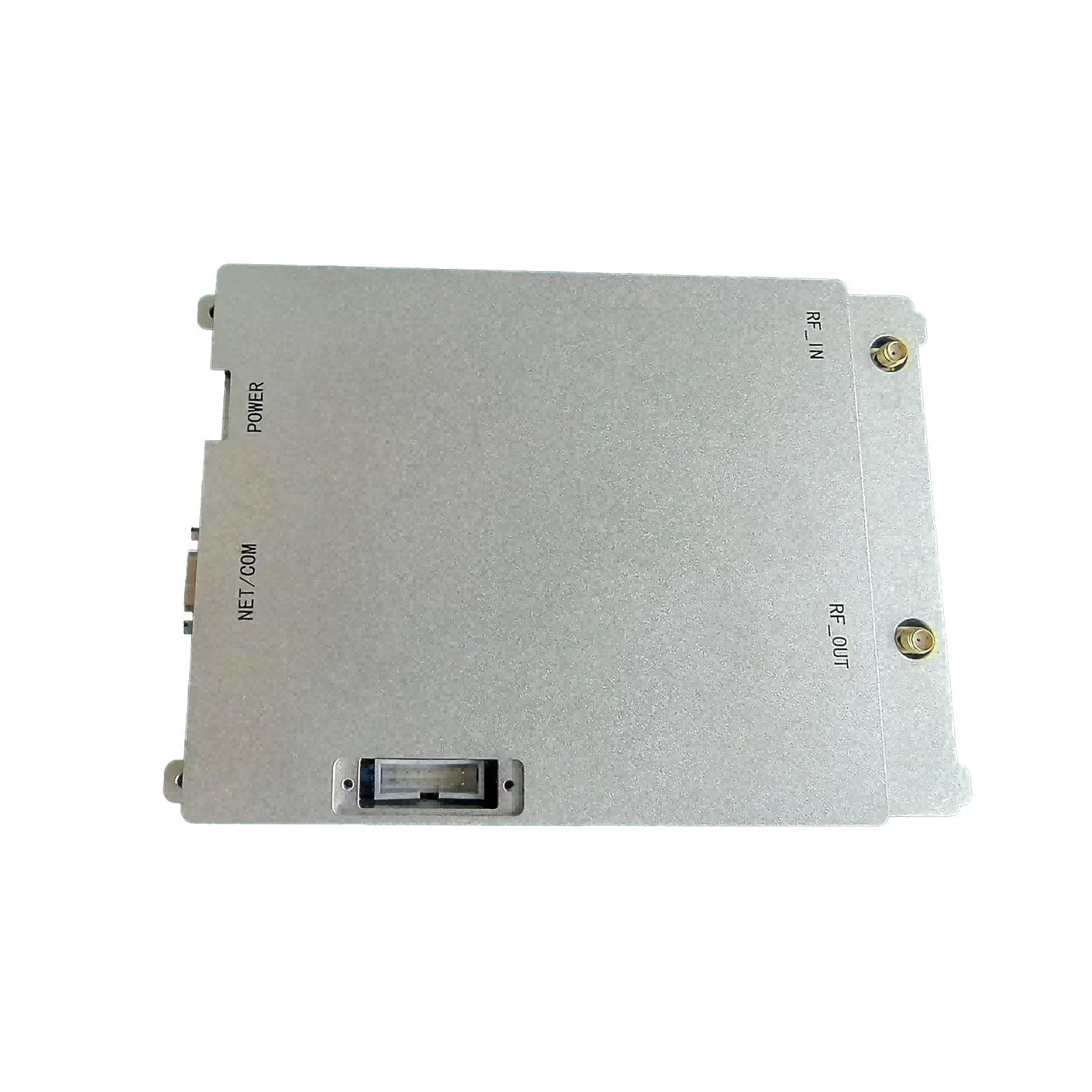
100W RF Power Amplifier - High-Efficiency Signal Boosting Solution
- Fundamental Principles of RF Power Amplification
- Technical Advancements in Modern 100W RF Systems
- Critical Performance Metrics and Reliability Standards
- Comparative Analysis of Leading Manufacturers
- Customization Approaches for Specialized Applications
- Practical Deployment Scenarios and Performance Data
- Selection Criteria for RF Power Amplifier Systems
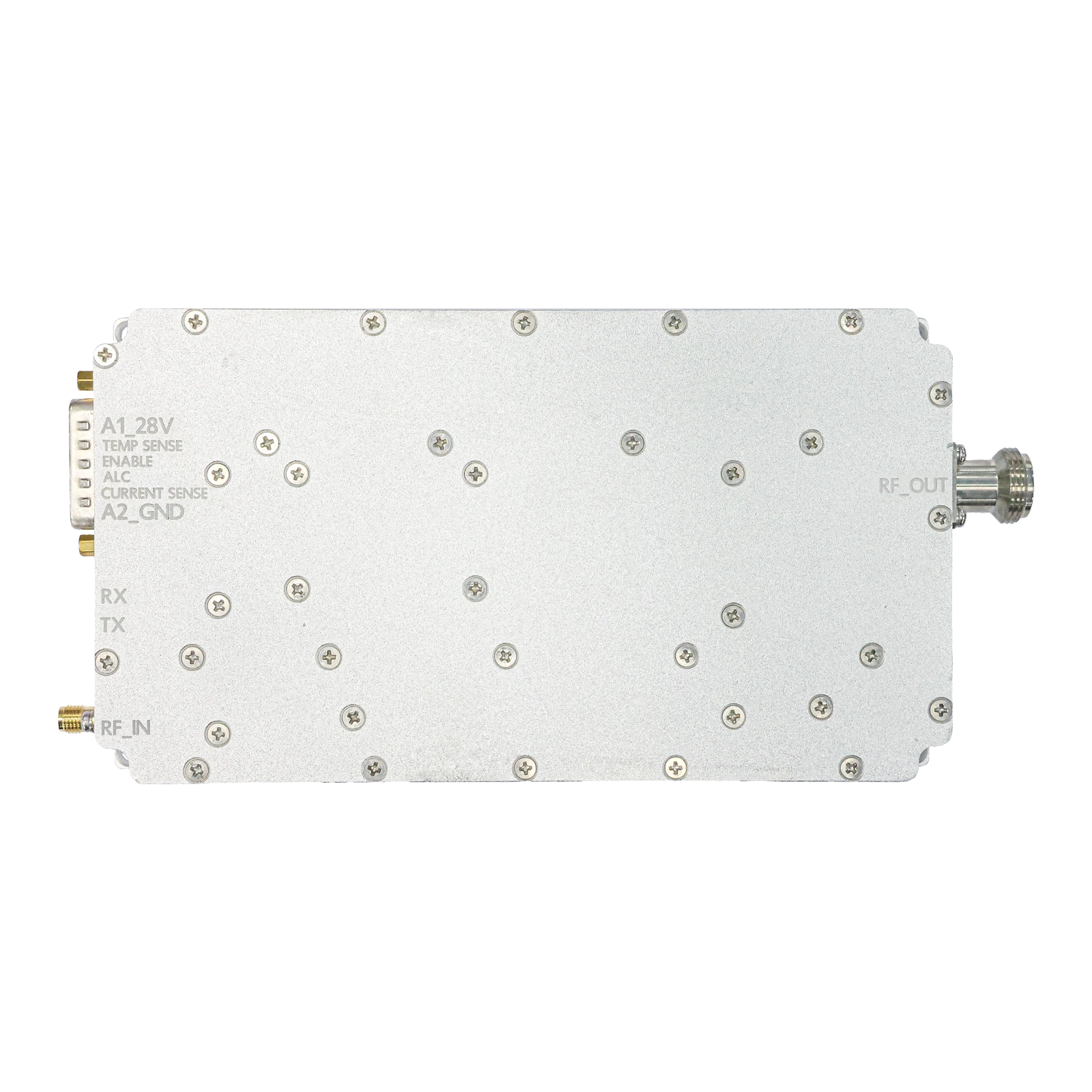
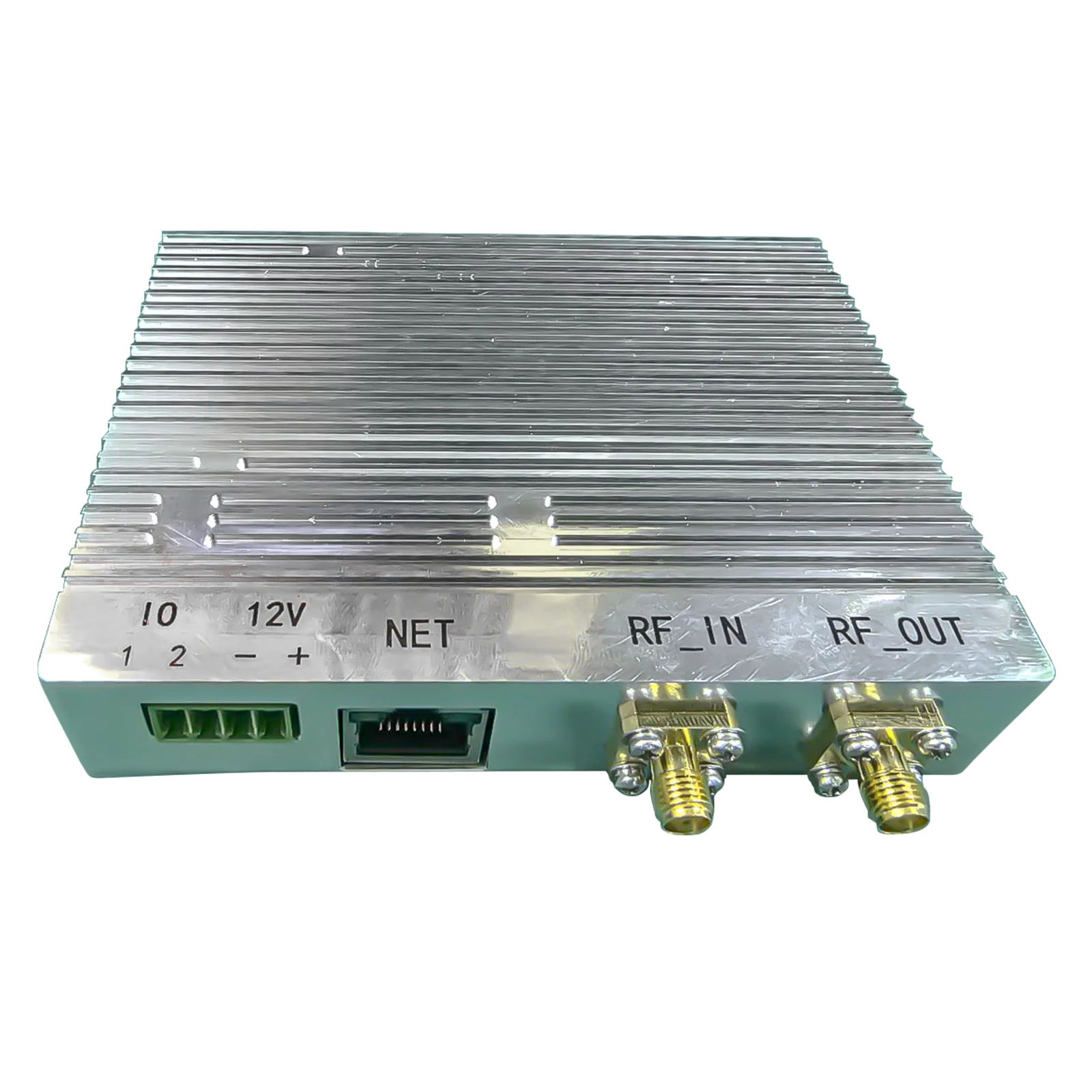
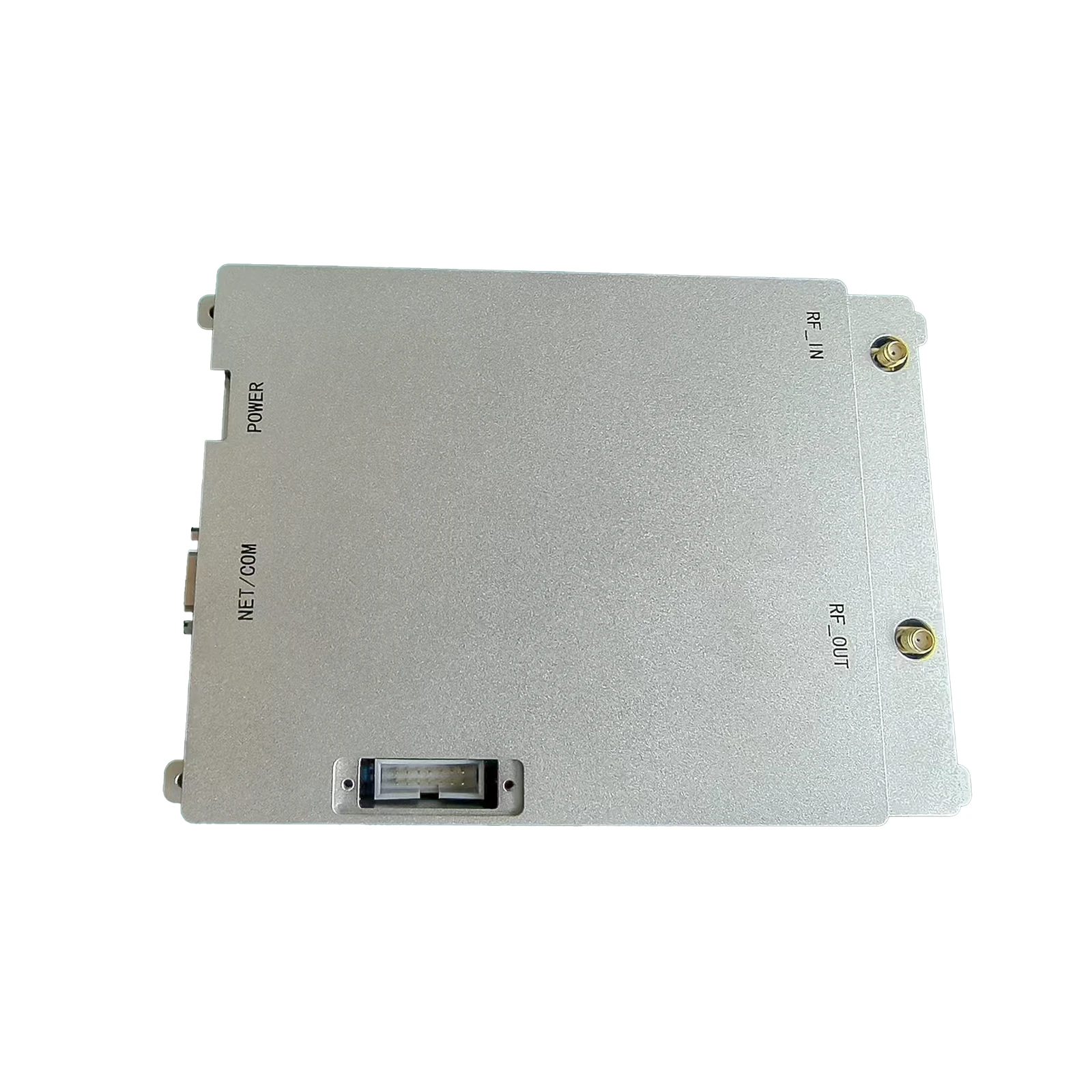
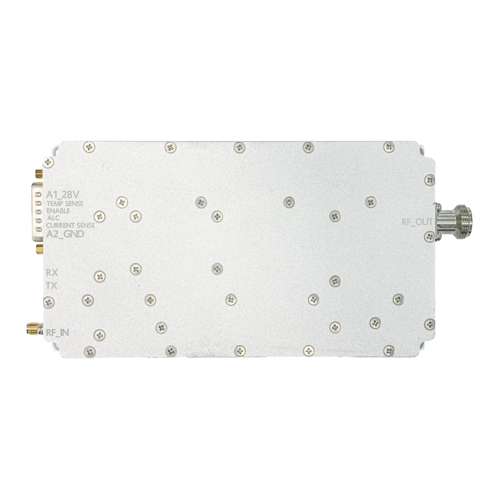
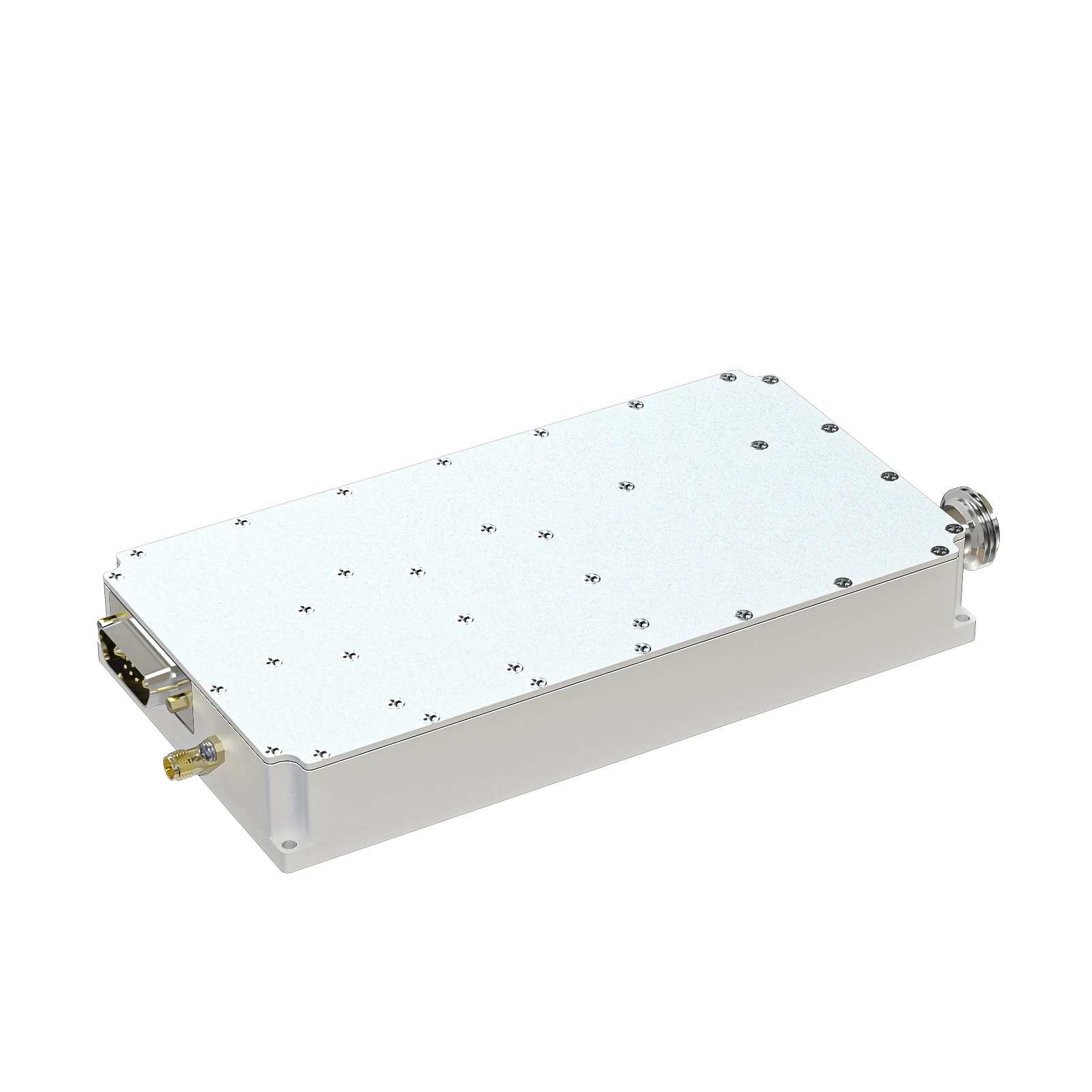
(100 watt rf power amplifier)
Introduction to 100 Watt RF Power Amplifier Systems
Radio Frequency (RF) power amplifiers form the backbone of modern wireless communication systems. The 100 watt power amplifier represents the optimal balance between transmission distance, signal integrity, and energy consumption. These devices convert low-power RF signals into higher-power transmissions across frequency ranges between 500 MHz and 6 GHz. Key design considerations include gain flatness (±1.5dB across operating bandwidth), harmonic suppression (>30dBc), and adjacent channel power ratio (ACPR) performance below -45dBc to prevent interference. Modern 100W designs incorporate GaN (Gallium Nitride) semiconductor technology, delivering 60-75% power-added efficiency compared to 35-50% in traditional GaAs counterparts. Thermal management systems dissipate approximately 150-200 watts of heat, maintaining operational junction temperatures below 175°C. This foundational technology enables critical applications from emergency broadcast systems to 5G infrastructure backhaul networks.
Innovations Driving Amplification Efficiency
Recent technological breakthroughs have transformed 100 watt RF power amplifier performance envelope. Gallium Nitride transistors now dominate high-power segments, delivering power densities exceeding 5W/mm compared to GaAs's 1W/mm limitation. Doherty amplifier topologies combined with digital pre-distortion (DPD) techniques achieve peak efficiency ratings above 68% while maintaining signal fidelity. Thermal innovations such as liquid-cooled baseplates reduce thermal resistance to 0.15°C/W, enabling sustained operation at full power output without derating. These amplifiers now incorporate smart protection circuits that automatically detect VSWR (Voltage Standing Wave Ratio) mismatches beyond 3:1 and reduce output power within milliseconds to prevent component damage. Additional advanced features include Ethernet-based remote monitoring interfaces that track over 25 operational parameters with accuracy thresholds of ±0.5dB for power measurement and ±1°C for temperature monitoring.
Performance Benchmarks and Operational Parameters
Evaluating power amplifier systems requires comprehensive metrics beyond basic wattage ratings. For 100W RF devices, key specifications include phase linearity (±3° variation) for complex modulation schemes, noise floor (-150dBc/Hz at 100kHz offset), and intermodulation distortion (IMD3 < -35dBc at PEP). The figure below illustrates critical performance characteristics:
Power Usage Across Modulation Types:
- Continuous Wave (CW) operation: 98-103W output
- WCDMA signals: 85-95W average output
- 256-QAM modulation: 75-82W average output
Accelerated lifespan testing demonstrates 100,000+ hours MTBF (Mean Time Between Failures) under 35°C ambient temperature conditions. Environmental testing standards ensure functionality across extreme conditions including -40°C cold starts, 100% humidity exposure, and resistance to 5g vibrational forces. Frequency-agile variants maintain ±0.5dB gain flatness across octave bandwidths while preserving spectral purity.
Manufacturer Comparison Analysis
| Manufacturer | Frequency Range | Gain (dB) | Efficiency (%) | Linearity | Dimensions | Price ($) |
|---|---|---|---|---|---|---|
| Broadcast Devices Inc. | 470-860 MHz | 54±1.5 | 73% Peak | IMD3: -42dBc | 3U Rack, 19" | 4,850 |
| RF Micro Solutions | 400-600 MHz | 49±1.0 | 68% Average | ACPR: -47dBc | Portable, 8x8x3" | 3,990 |
| Communication Dynamics | 1.8-2.2 GHz | 57±1.2 | 70% Peak | EVM: 2.5% | Desktop, 12x10" | 5,250 |
| Military Tech Systems | 0.5-6.0 GHz | 51±2.0 | 65% Average | Harmonics: -50dBc | 1U Ruggedized | 8,600 |
Performance differentiation among industry leaders reveals substantial engineering tradeoffs. Broadcast Devices specializes in optimized UHF solutions achieving record 73% efficiency through proprietary matching networks. RF Micro Solutions prioritizes compactness with their portable 100 watt RF amplifier featuring advanced forced-air convection exceeding standard thermal metrics. Communication Dynamics dominates cellular infrastructure integration with proprietary DPD algorithms. Military Tech Systems offers the broadest frequency coverage but requires premium pricing for specialized ruggedization and instantaneous bandwidth capabilities that meet DEF-STAN-59-411 standards.
Customized Application Integration
Implementing RF power amplifiers requires application-specific customization beyond off-the-shelf specifications. Technical adaptation typically addresses five key domains:
- Antenna Interface: Custom impedance matching networks optimize power transfer for unique antenna VSWR profiles
- Thermal Constraints: Liquid-cooled housings for base station installations versus convection-cooled options for vehicular deployments
- Spectral Requirements: Harmonic filtering configurations tailored to allocated frequency bands and national regulatory constraints
- Remote Monitoring: Integration of IoT sensors for predictive maintenance analytics under demanding operational profiles
Specialized variants include self-oscillating designs that eliminate external signal sources for fixed-frequency applications, reducing system complexity by 40% and power consumption by 15%. Industrial IoT implementations often employ adaptive bias controllers that dynamically adjust quiescent currents based on modulation characteristics, reducing idle power consumption by up to 30% during transmission gaps without compromising rise-time performance.
Field Performance Validation
Actual deployment scenarios validate design specifications under complex operating conditions. In cellular backhaul systems across the Philippines' mountainous regions, 100 watt rf amplifier systems maintained 99.992% availability during monsoon season despite temperature variations from 10°C to 45°C. Performance metrics across diverse scenarios:
- Satellite Communication (Marine Environment): 92W sustained output during 6-meter wave conditions with 95% availability
- Military Jamming Systems: 98W ERP at target frequency with <-55dBc spurious emissions during 72-hour continuous operations
- FM Broadcasting: 100W carrier stability within ±0.25dB during commercial power fluctuations exceeding ±15%
Data acquisition modules recorded less than 0.15dB gain compression during tropical deployment while maintaining spectral compliance with FCC/CE regulatory masks. Energy consumption analytics revealed a 19% reduction in power conversion losses when compared with earlier generation amplifiers during similar modulation schemes.
Selection Considerations for 100 Watt RF Power Amplifier
Selecting the optimal 100 watt amplifier requires balancing technical specifications against operational requirements. Beyond the fundamental frequency range and power output, critical evaluation factors include third-order intercept point (+50dBm minimum for communication-grade units), gain stability over temperature (±0.03dB/°C), and protection circuit response times (under 10μs for overvoltage conditions). Consideration of adjacent technical infrastructure includes control interface compatibility - RS232, Ethernet, CAN bus - and voltage requirements (48V DC for telecom standards versus 28V for aerospace). Total cost calculations must factor reliability indicators with high-end units demonstrating failure rates of 0.25% per 1,000 operational hours versus 1.2% in budget offerings. Implementing thorough validation testing at 110% rated power for 500 continuous hours effectively identifies potential field reliability issues while matching transient load characteristics preserves waveform integrity across demanding modulation environments.

(100 watt rf power amplifier)
FAQS on 100 watt rf power amplifier
Q: What are the typical applications of a 100 watt RF power amplifier?
A: A 100 watt RF power amplifier is commonly used in amateur radio systems, broadcast transmitters, and wireless communication infrastructure to boost signal strength for long-range transmission.
Q: How does a 100 watt RF amplifier differ from a 2 watt RF power amplifier?
A: The 100 watt amplifier provides significantly higher output power for long-distance communication, while a 2 watt RF power amplifier is suited for low-power applications like small transceivers or test equipment.
Q: What cooling methods are recommended for a 100 watt RF power amplifier?
A: Active cooling (e.g., fans) or large heatsinks are essential to manage heat dissipation in 100 watt RF amplifiers, ensuring stability and preventing thermal shutdown during continuous operation.
Q: Can a 100 watt RF amplifier be used for HF or VHF frequencies?
A: Yes, many 100 watt RF amplifiers support HF (1.8-30 MHz) and VHF (30-300 MHz) bands, but verify the frequency range and impedance matching specifications for your specific use case.
Q: What safety precautions are needed when operating a 100 watt RF power amplifier?
A: Ensure proper grounding, avoid RF exposure by maintaining safe distances, and use RF-rated connectors/cables to prevent arcing or damage at high power levels.
-
09 March 2021 21 May 2025
-
09 March 2021 16 May 2025
-
09 March 2021 16 May 2025
-
09 March 2021 16 May 2025
-
09 March 2021 16 May 2025
-
09 March 2021 21 May 2025
-
09 March 2021 25 Dec 2024
-
09 March 2021 14 Oct 2022
-
09 March 2021 25 Dec 2024


