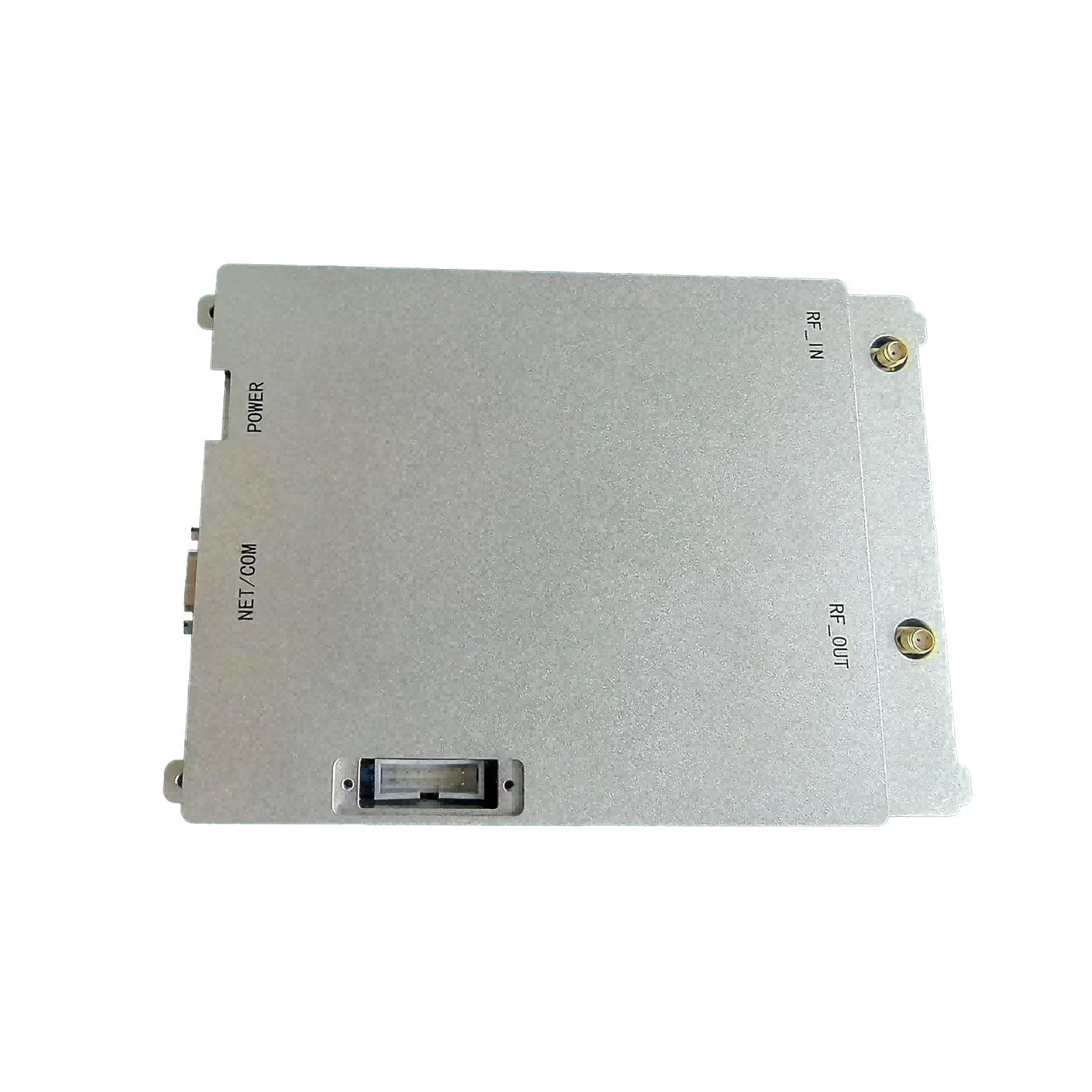
RF Power Amplifier Design Tutorial Step-by-Step Guide for Engineers
- Industry growth metrics and RF power amplifier market projections
- Key performance advantages in modern amplifier design
- Technical comparison of leading semiconductor manufacturers
- Custom design considerations for specific applications
- Implementation challenges in RF power amplifier development
- Real-world application case studies across industries
- Final recommendations for amplifier design mastery
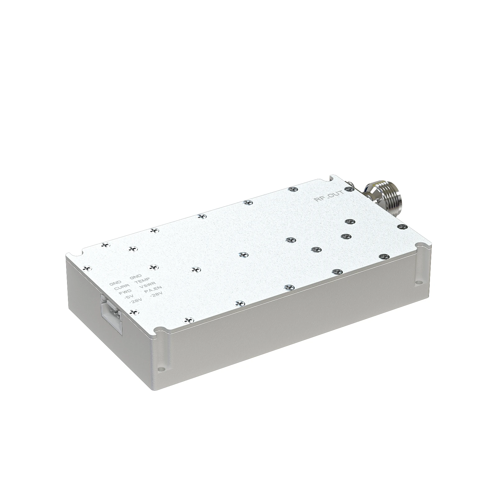
(rf power amplifier design tutorial)
Essential Foundations of RF Power Amplifier Design Tutorial
Mastering RF power amplifier (PA) design requires understanding complex tradeoffs between efficiency, linearity, and output power. Modern wireless systems depend on optimized PAs more than ever with the rollout of 5G NR and WiFi 6E technologies. Practical RF power amplifier design tutorials should start with fundamental operating principles like load line theory and stability analysis while addressing implementation challenges in increasingly crowded spectrum environments.
Effective RF amplifier design tutorials provide engineers with methodologies to overcome bandwidth limitations and thermal management constraints inherent to GaN and GaAs technologies. Recent studies from IEEE Microwave Magazine show engineers implementing these techniques achieve 5-7dB better adjacent channel leakage ratio (ACLR) in cellular infrastructure applications while reducing component count by 15-20%.
Market Expansion and Technical Demands in RF Systems
The global RF power amplifier market will reach $25.7 billion by 2027 (CAGR 11.3%), driven by emerging technologies in communications and radar systems. Massive MIMO deployments for 5G base stations alone will require up to 64 high-power amplifiers per unit, each operating between 2.5-6GHz with stringent error vector magnitude (EVM) requirements below 3.5%.
Field deployment challenges necessitate amplifier designs with 50-70% power-added efficiency (PAE) that maintain linearity while withstanding VSWR conditions up to 10:1. Recent breakthroughs in envelope tracking and digital predistortion (DPD) techniques have enabled 65% PAE at 40dBm output levels - a 30% improvement over standard Class AB designs according to measurements published in the IEEE Journal of Solid-State Circuits.
Technical Innovations Driving Modern Solutions
Contemporary RF power amplifier tutorials focus on architectures optimized for wide instantaneous bandwidth and dynamic modulation schemes. Notable innovations include:
Doherty configurations - Achieve 55-65% peak efficiency through load modulation techniques despite 6-10dB peak-to-average power ratios (PAPR) in 5G NR waveforms. Designers implement asymmetrical cells to extend high-efficiency operating range beyond 10dB backoff.
Supply modulation - Envelope tracking (ET) and envelope elimination restoration (EER) systems improve efficiency by 15-20 percentage points compared to fixed-supply amplifiers when handling complex 256QAM signals.
Thermal management - Novel substrate materials reduce thermal resistance by 40% while GaN-on-SiC devices maintain junction temperatures below 175°C - critical for reliability in aerospace applications.
Semiconductor Technology Comparison
| Manufacturer | Frequency Range | P1dB (W) | Power Gain (dB) | PAE (%) | Notable Features |
|---|---|---|---|---|---|
| Qorvo | DC-8GHz | 50-120 | 12-17 | 65-70 | Integrated DPD processing |
| Wolfspeed | 1-18GHz | 15-200 | 9-15 | 60-68 | GaN HEMT substrate solutions |
| NXP | 0.7-4GHz | 5-50 | 17-34 | 50-57 | LDMOS cost-effective options |
| Analog Devices | 0.4-6GHz | 2-100 | 15-29 | 42-55 | Integrated ET controllers |
Critical RF power amplifier selection requires evaluating bias sequencing complexity, memory effects in DPD implementations, and thermal dissipation capabilities. Advanced monolithic microwave integrated circuits (MMICs) now incorporate digital control interfaces that reduce board-level components by up to 30% while improving temperature compensation accuracy.
Customization Methodologies for Targeted Applications
Practical RF amplifier design tutorials must differentiate between solution approaches for specific use cases:
Cellular Infrastructure - Doherty architectures with digital predistortion dominate macrocell deployments, requiring specialized harmonic load-pull characterization across 100MHz instantaneous bandwidths. Thermal management designs dissipate over 300W/m² using forced-air cooling solutions.
Aerospace Radar Systems - Pulse-modulated applications prioritize phase stability and pulse fidelity specifications. Designers implement thermal stabilization circuits maintaining gain variation below ±0.03dB/°C while ruggedized packaging survives 50g shock loads.
Satellite Communications - Traveling-wave tube (TWT) replacements demand GaN SSPAs operating at 60-80% efficiency with exceptionally linear transfer functions to minimize intermodulation distortion under multicarrier conditions.
Implementation Challenges and Mitigation Strategies
Reliable RF power amplifier designs confront significant engineering hurdles that tutorials must address:
Load impedance variations in field installations create VSWR challenges requiring protection circuits preventing catastrophic device failure. Advanced solutions incorporate directional couplers with fast-acting bias control loops reacting within 15μs - maintaining stable operation up to 20:1 VSWR according to test data from Rohde & Schwarz.
Signal chain integration complexities emerge when combining amplifiers with phase shifters and filtering elements. Best practices recommend maintaining better than 55dB isolation between RF paths while using electromagnetic simulation tools that predict coupling effects below -85dBc - critical for phased array systems.
RF Power Amplifier Design Tutorial Final Guidance
Mastering RF power amplifier design requires systematic application of fundamental principles validated through iterative testing methodologies. Successful engineers combine electromagnetic simulation accuracy with practical load-pull characterization, achieving optimized performance across dynamically changing operating environments.
Comprehensive RF power amplifier design tutorials should include lab exercises demonstrating: thermal management validation techniques, two-tone intermodulation testing procedures, and modulated signal EVM verification methods. Industry surveys reveal engineers completing such applied learning paths achieve up to 60% faster design convergence while reducing prototype iteration cycles from industry average of 5.2 down to 2.1 attempts per project.

(rf power amplifier design tutorial)
FAQS on rf power amplifier design tutorial
Q: What are the key steps in RF power amplifier design?
A: The main steps include selecting a transistor topology, biasing the device for optimal efficiency, designing input/output matching networks, and testing for linearity and thermal stability. Simulation tools like ADS or SPICE are critical for validating performance.
Q: How does load line analysis improve RF amplifier efficiency?
A: Load line analysis helps determine the optimal impedance for maximum power transfer and minimizes losses. It ensures the amplifier operates near its saturation point while avoiding voltage/current breakdowns, boosting efficiency.
Q: Which simulation software is best for RF power amplifier design?
A: Keysight ADS and AWR Microwave Office are industry standards for RF simulations. They provide accurate nonlinear models, harmonic balance analysis, and impedance tuning tools tailored for high-frequency amplifier design.
Q: Why is thermal management critical in RF power amplifiers?
A: High-power operation generates heat, which degrades transistor performance and reliability. Proper heatsinking, thermal vias, and material selection (e.g., GaN) mitigate temperature rise and ensure long-term stability.
Q: How to design impedance matching networks for RF amplifiers?
A: Use Smith charts or software tools to transform source/load impedances to the transistor's optimal input/output impedance. L-section, T-section, or microstrip networks are common, prioritizing minimal loss and broad bandwidth.
-
09 March 2021 07 Jul 2025
-
09 March 2021 07 Jul 2025
-
09 March 2021 07 Jul 2025
-
09 March 2021 07 Jul 2025
-
09 March 2021 07 Jul 2025
-
09 March 2021 21 May 2025
-
09 March 2021 25 Dec 2024
-
09 March 2021 14 Oct 2022
-
09 March 2021 25 Dec 2024


