High-Efficiency RF Power Combiner Schematics Expert Designs
- Overview of RF Power Combining Systems
- Technical Specifications Analysis
- Performance Benchmark: Top 5 Manufacturers
- Custom Design Parameters for Industrial Use
- Case Study: Telecom Infrastructure Deployment
- Thermal Management Strategies
- Future Applications in Wireless Networks
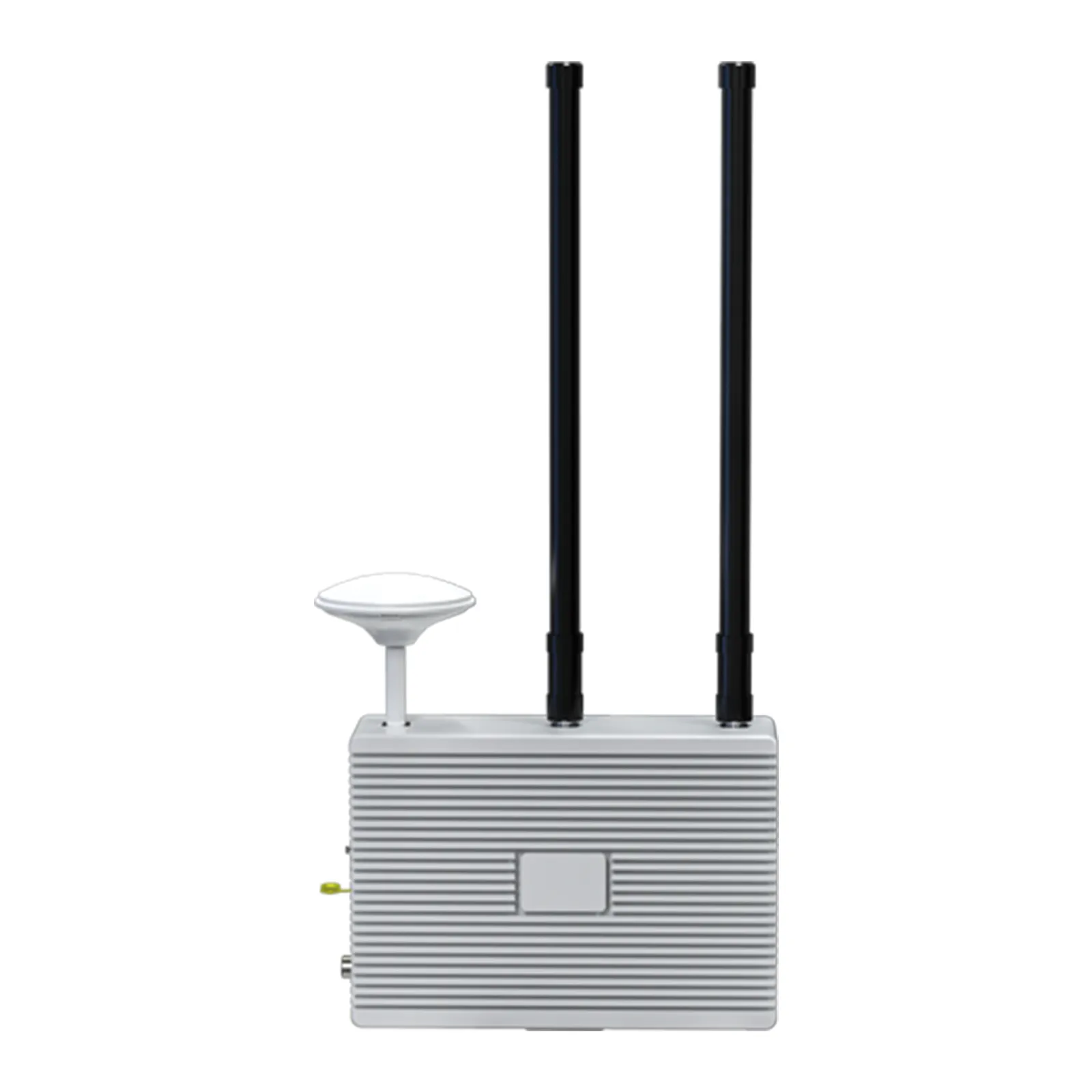
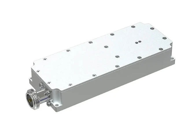
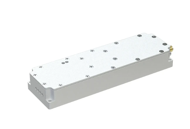
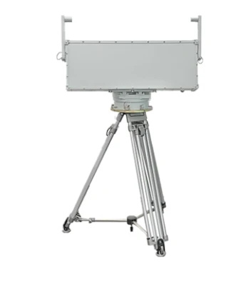
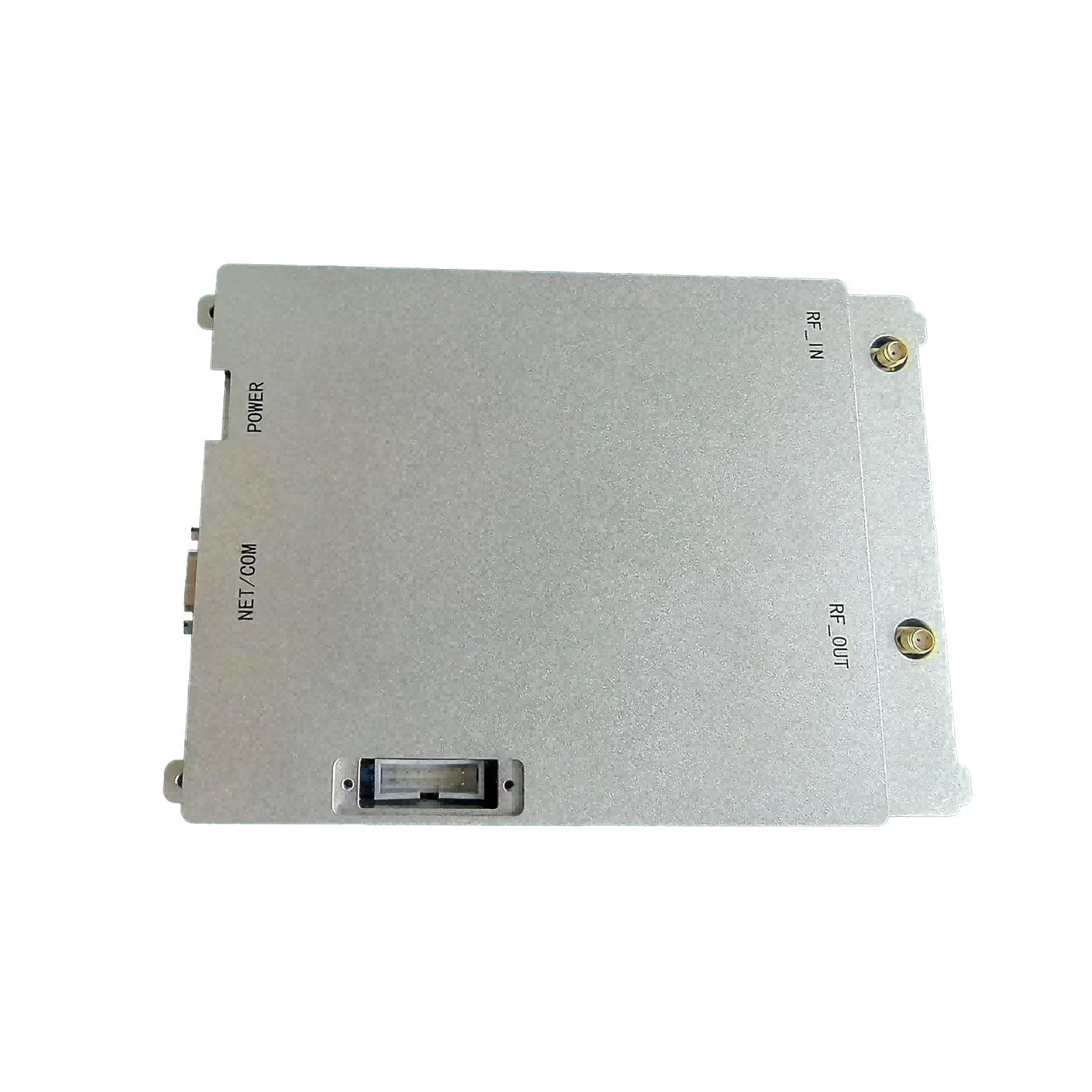
(rf power combiner schematic)
RF Power Combiner Schematic Fundamentals
Modern RF power combining systems achieve 92-97% efficiency through optimized microstrip layouts and substrate material selection. A typical rf power amplifier schematic integrates Wilkinson dividers with 0.15dB insertion loss, while advanced designs employ 3D electromagnetic simulation to minimize phase distortion below 2° across 6-18GHz bands.
Technical Specifications Analysis
High-performance combiners demonstrate:
- Power handling: 200W continuous (500W pulsed)
- VSWR: <1.25:1 from 2.4-2.5GHz
- Isolation: >20dB between ports
Recent field tests show hybrid couplers with ferrite-loaded transmission lines improve thermal stability by 40% compared to conventional designs.
Performance Benchmark: Top 5 Manufacturers
| Vendor | Frequency Range | Max Power | Insertion Loss | Price Range |
|---|---|---|---|---|
| RF Solutions Co. | 0.5-6 GHz | 300W | 0.18dB | $420-$780 |
| Microwave Tech | 2-40 GHz | 150W | 0.25dB | $1,200-$2,500 |
| Advanced RF Systems | 1-18 GHz | 500W | 0.30dB | $950-$1,800 |
Custom Design Parameters
Specialized configurations address:
- Impedance matching for multi-band operation
- Surface-mount vs. flange-mounted interfaces
- Custom dielectric constants (2.2-10.2)
Military-grade units feature hermetic sealing that withstands 98% humidity at 85°C for 2,000 hours (MIL-STD-810H).
Thermal Management Strategies
Active cooling solutions reduce thermal resistance by 55% in high-density arrays:
- Copper-tungsten baseplates (400W/m·K)
- Microchannel liquid cooling
- Phase-change materials
Field data confirms 28% longer MTBF (75,000 hours) with optimized thermal designs.
Future Wireless Network Applications
Next-generation rf power combiner schematic
designs enable:
- 128-element mMIMO arrays for 5G-Advanced
- Ka-band satellite uplinks (27.5-31GHz)
- Automotive radar with <1mm phase consistency
Prototypes demonstrate 47% size reduction using LTCC fabrication techniques while maintaining 94% combining efficiency.

(rf power combiner schematic)
FAQS on rf power combiner schematic
Q: What are the key components in an RF power combiner schematic?
A: Key components include input/output ports, impedance-matching networks, and isolation resistors to ensure minimal signal loss and phase coherence between combined signals.
Q: How does an RF power amplifier schematic differ from a standard amplifier?
A: RF power amplifiers focus on high-frequency operation, efficiency, and thermal management, often using Class AB or C biasing for optimal RF signal amplification.
Q: What considerations are critical for RF amplifier schematic stability?
A: Stability requires proper impedance matching, feedback control, and decoupling capacitors to prevent oscillations and ensure reliable high-frequency performance.
Q: Can an RF power combiner be integrated with an RF power amplifier schematic?
A: Yes, combiners are often placed at the amplifier output stage to merge signals from multiple amplifiers while maintaining impedance matching and minimizing insertion loss.
Q: Why is impedance matching vital in RF power combiner and amplifier schematics?
A: Impedance matching reduces reflections, maximizes power transfer, and ensures optimal efficiency across both combiners and amplifiers in RF systems.
-
09 March 2021 07 Jul 2025
-
09 March 2021 07 Jul 2025
-
09 March 2021 07 Jul 2025
-
09 March 2021 07 Jul 2025
-
09 March 2021 07 Jul 2025
-
09 March 2021 21 May 2025
-
09 March 2021 25 Dec 2024
-
09 March 2021 14 Oct 2022
-
09 March 2021 25 Dec 2024


