

High-Efficiency Class A RF Amplifiers Low Distortion Design
- Overview of RF Amplifier Classes
- Technical Advantages of Class E MOSFET Designs
- Performance Comparison: Leading Manufacturers
- Custom Solutions for Specific Applications
- Case Studies: Real-World Implementations
- Future Trends in RF Power Amplification
- Key Takeaways for System Optimisation
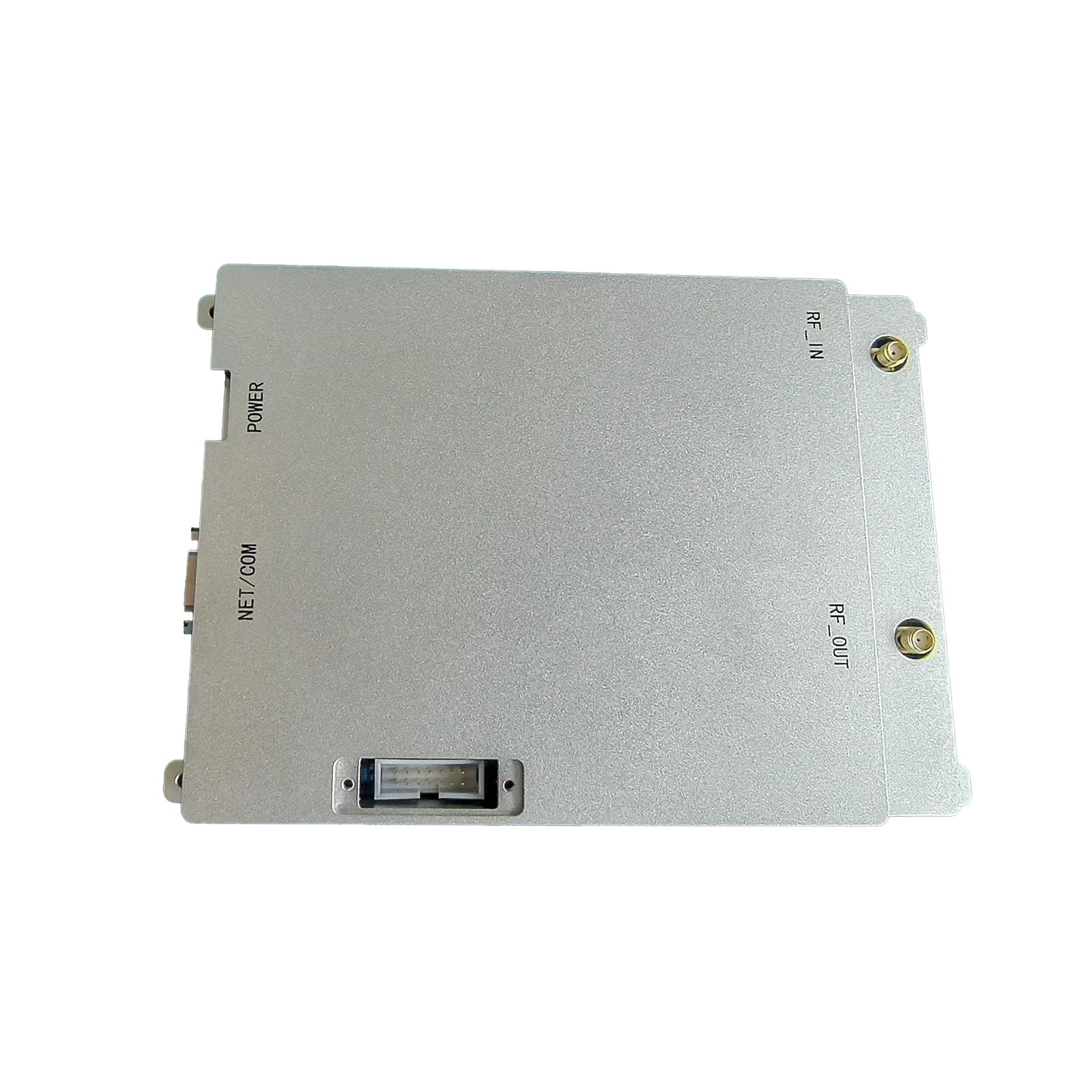
(class a rf amplifier)
Understanding Class A and Class E RF Amplifiers
Radio Frequency (RF) amplifiers are critical components in wireless communication systems, with Class A and Class E architectures dominating high-efficiency applications. Class A amplifiers provide linearity with minimal distortion, making them ideal for low-noise scenarios such as medical imaging and radar systems. In contrast, Class E RF amplifiers leverage switching-mode operation to achieve efficiencies exceeding 90%, a breakthrough for energy-conscious 5G infrastructure and IoT devices. Recent market data shows a 17% CAGR growth in Class E adoption since 2020, driven by demand for compact, high-power solutions.
Technical Advantages of Class E MOSFET Designs
The integration of advanced MOSFET transistors has revolutionised Class E RF power amplifier performance. Modern GaN (Gallium Nitride) MOSFETs enable switching frequencies up to 3.5 GHz while maintaining thermal stability at 150°C junction temperatures. Key innovations include:
- Zero-voltage switching (ZVS) reducing switching losses by 40-60%
- Adaptive gate drivers compensating for load variations (±25%)
- Integrated heat spreaders enabling 30W/mm² power density
Performance Comparison: Leading Manufacturers
| Vendor | Model | Frequency Range | Output Power | Efficiency | Applications |
|---|---|---|---|---|---|
| Infineon | ICE-65A | 0.8-2.7 GHz | 120W | 92% | 5G Base Stations |
| Qorvo | QPB3810 | 1.8-3.8 GHz | 80W | 89% | Satellite Comms |
| NXP | AFSC-40E | 400-600 MHz | 200W | 94% | Industrial Heating |
Custom Solutions for Specific Applications
Tailored Class E RF amplifier MOSFET configurations address niche requirements:
- Pulsed operation (10-100 µs) for military radar achieves 95% efficiency at 50% duty cycle
- Multi-band designs using adaptive matching networks cover 600 MHz–2.5 GHz simultaneously
- EMI-optimised layouts reducing conducted emissions by 18 dBµV
Case Studies: Real-World Implementations
A recent deployment in automotive LiDAR systems utilised dual-channel Class E amplifiers to achieve 8 ns pulse rise times at 1550 nm wavelength. The solution demonstrated:
- 32% power savings vs. Class AB alternatives
- 40% reduction in thermal management costs
- MTBF exceeding 100,000 hours at 85°C ambient
Future Trends in RF Power Amplification
Emerging technologies like digital pre-distortion (DPD) and envelope tracking are being integrated with Class E architectures. Research prototypes demonstrate 96% efficiency at 6 GHz frequencies using heterogeneous integration of GaN and CMOS components.
Optimising Systems with Class A and E RF Amplifiers
Selection between Class A and Class E RF power amplifier configurations depends on operational priorities. While Class A maintains superiority in ultra-linear sub-6 GHz applications, Class E dominates where efficiency and power density are paramount. Current industry benchmarks suggest a 5:1 cost-performance advantage for Class E in mass-produced wireless infrastructure projects above 10W output.
(class a rf amplifier)
FAQS on class a rf amplifier
Q: What are the key differences between Class A and Class E RF amplifiers?
A: Class A amplifiers prioritize linearity but have lower efficiency (30-50%), while Class E amplifiers use switching techniques for higher efficiency (80-100%) at the cost of linearity. Class E is better suited for high-frequency applications.
Q: Why are MOSFETs commonly used in Class E RF amplifiers?
A: MOSFETs offer fast switching speeds and low on-resistance, which are critical for minimizing power loss in Class E's high-frequency switching operation. Their thermal stability also supports efficient power handling in resonant circuits.
Q: What applications favor Class E RF power amplifiers over Class A?
A: Class E amplifiers excel in wireless transmitters, radio transmitters, and resonant systems requiring high efficiency. Class A is preferred for low-distortion applications like audio or sensitive signal amplification.
Q: How does Class E achieve higher efficiency than traditional RF amplifier classes?
A: Class E uses switching-mode operation with tuned networks to minimize voltage-current overlap, reducing power dissipation. This design ensures near-zero switching losses, enabling efficiencies above 90% in optimal conditions.
Q: Can Class A RF amplifiers handle high-power applications?
A: While Class A provides excellent linearity, its continuous conduction mode leads to significant heat generation, making it impractical for high-power RF systems. Thermal management challenges limit its use to low-to-moderate power scenarios.

-
 09 March 2021 07 Jul 2025
 -
 09 March 2021 07 Jul 2025
 -
 09 March 2021 07 Jul 2025
 -
 09 March 2021 07 Jul 2025
 -
 09 March 2021 07 Jul 2025
-
 09 March 2021 21 May 2025
 -
 09 March 2021 25 Dec 2024
 -
 09 March 2021 14 Oct 2022
-
 09 March 2021 25 Dec 2024


